|
|
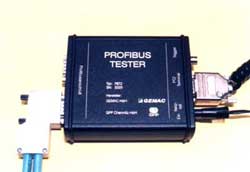
측정요소
- Incorrect
bus terminations
- Inadequate
transmission levels
- High
contact resistance
- Poor
signal quality (excessive length of the spur line)
-
Use of unsuitable cables
-
Laying of cables in the vicinity of strong fields
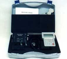
공급범위
- PROFIBUS-Tester
PBT2
- PC-software
CD
-
User's manual
- Adapter-Cards
(2 pieces)
- PROFIBUS
adapter cable of oscilloscope connection
-
Zero-modem cable
-
AC/DC adapter
|
|
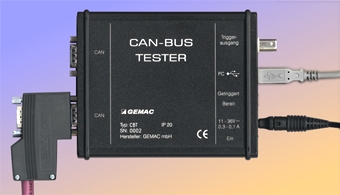
측정요소
- Incorrect
bus terminations
- Poor
signal quality (excessive length of stub lines)
-
Inadequate transmission levels (pre-damaged bus drivers)
- Use
of incorrect cables
- Excessive
cable length
- Excessive
high contact resistance due to aging/corrosion
- Failure
of all kinds
- Cable
routing in environments subject to substantial interference.
공급범위
- CAN-Bus-Tester
- CBT
CAN adapter cable, 30 cm long, 4 pin, with PG socket
- DeviceNet
A1 cable (Open Connector)
- DeviceNet
A2 cable (Sealed Micro Connector, M12)
-
USB cable, 3 m
- Adapter
board, for the simple connection of the oscilloscope probes
- AC/DC
adapter with a wide-range input
- User
manual, including CD Case
|